![]() |
| From Uniselector Clock |
![]() |
| From Uniselector Clock |
![]() |
| From Uniselector Clock |
![]() |
| From Uniselector Clock |

![]() |
| From gadgets |
![]() |
| From gadgets |

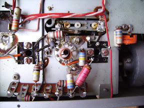
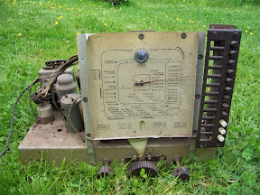
leads. Given the style of transformer I've got, this seemed worth a check. So I opened it up carefully removed the outer layers of tape. In the picture you might be able to make out that the connections to the yellow wires are good but all four strands that should have been connected to the red centre-tap had failed. There was some charring and a little bit further away from where the connection had been some green traces. Further poking around and I had all four strands again. A little shorter than originally, but by scraping off the enamel I was able to test for continuity. Three of the four windings were OK. I don't know enough about transformer winding to know why each half of the primary was made up of two parallel w
indings, or why for the half that still had two good windings (I presume they were both good) one had a higher resistance than the other. Anyway I decided to use the two of the three good windings with the nearest resistances. Put it back together, and hey presto, a working "five - ten" with its original transformer returned. It probably can no longer safely deliver the full ten watts, but that's not really a problem. 
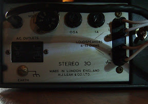
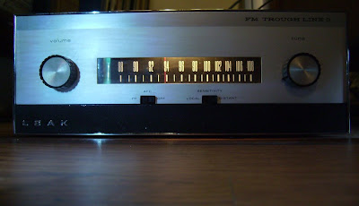
Over the last week I've spent evenings removing bad components and replacing with good ones. I found a few old Dubilier 0.1uF paper in oil capacitors that looked sound and measured OK on the test meter, so I've decided to try them. They certainly look the part. I decided it best to buy new electrolytics (except for the large HT filter cap - expensive) - Rifa's from RS look good and have decent specs.


One of my colleagues has just given me this valve (tube) amplifier built from a kit based on the Mullard Five-Ten design published back in 1954. Though this design is still being built by audio enthusiasts today, it seems this one is the genuine 1954 article. It's far from working condition though, so it's going to need a fair bit of work and a few replacement parts.
Here are a few more "before" photos. Things to note are that this kit uses the higher power rectifier option of the GZ30. The quality of construction of the chassis is good, so it was certainly built from a kit. The quality of the build is competent, but not great.
From the rear we see the two EL84 output valves, these look as though they've been very, very, hot and a check of the output transformer reveals the primary is open circuit. Between the output valves can be seen the ECC83 phase splitter and behind that the EF86.
From the underside we can see that there are some very old electrolytic and paper capacitors. Note that the dates on these are "JUL 53".
A closer view of the hole for the missing Bulgin mains connector. It seems there was once an earth tag here that has been replaced with a picture hook!
When I bought my first Trough Line 3 on Ebay a few weeks ago I did a little googling and found this article on replacing the stereo decoder in the stereo version and this one on an external decoder. It struck me that
converting a mono tuner to stereo might be a fun project that could be achieved fairly cheaply with salvaged components. All I needed was a tuner with a stereo decoder, which I had. Fortunately for the Sony, before I ripped it apart an older manually tuned Chinon receiver came up on Ebay locally, so I grabbed it for a fiver. Here it is accepting the multiplex output from the Trough Line.
Being a fairly ancient receiver, mid 70s I guess, the stereo demultiplexer chip was the only IC in the box, so fairly easy to spot, a mix of tracing the wiring, from mono/stereo switch, stereo indicator lamp (N.B. lamp, not LED), voltage checks and poking the pins with the CRT revealed what did what and the fact that it used a single 12V supply. I reckoned the easiest way to get it into the Trough Line would be to cut out what I needed from the circuit board using a hacksaw. So that's what I did! Here it is with a voltage doubler power supply taking 6.3V a.c. from the Trough Line heater supply.
So far, so good. Now to try and fit it in the Trough Line. The obvious
thing to do is to put it where the decoder is fitted in the stereo version. Wow, it fits! But it's a tight fit. Looking at the board more closely reveals that the tallest component is the smoothing cap for the regulated power supply. A modern cap of the same value taken from an old PC motherboard is half the size!Initial impressions of the first buy was that the sensitivity really is very low indeed, but it sounds great. The accepted audiophile solution is a big outdoor aerial. Fair enough, but are there alternatives, e.g. using a decent low noise RF amplifier? This was to be my first experiment with my newly acquired Trough Line 3, but then I saw an opportunity to acquire another very cheaply, albeit with no valves. Rummaging through my boxes of valves revealed that I had spares for everything, including the tuning indicator, except for the ECC84. So what is an ECC84 and did I have a suitable alternative? Looking at the circuit diagram I could see it was the first RF stage, but the circuit diagram was hard to read so I looked at the circuit for the stereo version. Hey, it uses a different valve, the ECC88, these I have.
ECC84, PCC84, ECC88, E88CC, PCC88 - what's the difference? If like me you've got a lot of old valves from old TV receivers, radios, and test equipment you probably don't have any spare ECC84s, but you may well have a few of each of the others. The good news is, they're all usable in early Trough Lines that use the ECC84, though some modification to the wiring of the Trough Line will be needed to use any of the 88s. It seems the ECC88 was an improved replacement for the ECC84, though the base connections aren't exactly the same. It also needs a slightly higher anode current. To check this without modifying the Trough Line I put together a simple adaptor. Here's the circuit.
And here's what it looks like.

And yes, it works! In fact it works very well, bringing in stations that couldn't be received at all with the ECC84. So I'm making this a permanent change to my first Trough Line. Hopefully nobody reading this will imagine I have any special powers or knowledge; all the information required to put together the adaptor can be extracted from the two circuit diagrams, but to be completely sure I checked the valve specs at the Virtual Valve Museum. Here you can also find details of the other valves I mentioned. It's worth noting that they aren't exact equivalents, since ECC84 and PCC84, etc. were designed for slighlty different uses and have different heaters.
Some explanation is possibly required regarding the heaters. The standard heater voltage for mains powered radios from about 1940 (earlier in the USA) was 6.3V. However for AC/DC sets and TVs the heaters were connected in series and so valves were designed to all draw the same current. Valves with a first letter 'E' are for parallel use at 6.3V, whereas those with a first letter
'P' are for serial use at 300mA. What you'll find is that for all these valves the heater voltage and current is within 10%, so for practical purposes they are all usable at 6.3V, and most likely all but the ECC88 are usable at 300mA (I've not tried this). Note this is not generally true for E and P valves, especially not output valves. Other heater variants are also possible, for example a UCC84 would have a 100mA heater.
Before -
And after -
I've seen PCC88 as substitution before. Though these are radio frequency (VHF) amplifier cascode triodes they were used unstead of the last ECC82 in my Ferrograph tape recorder when it was built. I'm not sure why though. What this does show is that the two triodes in the (E/P)CC88 are the same, this doesn't seem to be the case for (E/P)CC84.

